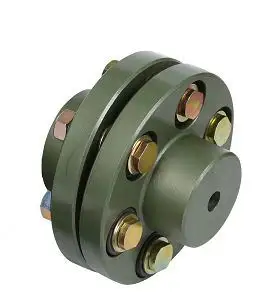
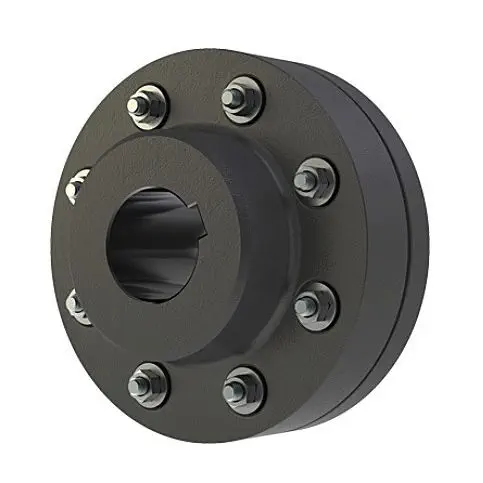
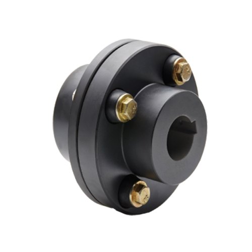
Product Description
Dedicated Couplings Adaptors for Ductile Iron Pipes ISO 2531/EN545 EN 14525, ANSI/AWWA C219
Description
SYI can supply the Dedicated Couplings dedicated Couplings, dedicated to connect the ductile iron pipe (upto DN2200)
SYI Dedicated Couplings DIMENSIONS
|
CHINAMFG S. N. |
DN |
pipe O.D. |
O.D. Tolerance |
D2 |
H |
L |
Min. pipe end prepared length |
|
|
|
mm |
|||||||
|
DC40 |
40 |
56 |
+1.0 |
-3.0 |
120 |
102 |
166 |
100 |
|
DC50 |
50 |
66 |
+1.0 |
-3.0 |
126 |
102 |
166 |
100 |
|
DC60 |
60 |
77 |
+1.0 |
-3.0 |
135 |
102 |
166 |
100 |
|
DC65 |
65 |
82 |
+1.0 |
-3.0 |
156 |
102 |
166 |
100 |
|
DC80 |
80 |
98 |
+1.0 |
-3.0 |
184 |
102 |
166 |
100 |
|
DC100 |
100 |
118 |
+1.0 |
-3.0 |
205 |
102 |
166 |
100 |
|
DC125 |
125 |
144 |
+1.0 |
-3.0 |
232 |
102 |
166 |
100 |
|
DC150 |
150 |
170 |
+1.0 |
-3.0 |
264 |
102 |
173 |
100 |
|
DC200 |
200 |
222 |
+1.0 |
-3.5 |
315 |
102 |
173 |
100 |
|
DC250 |
250 |
274 |
+1.0 |
-3.5 |
374 |
102 |
173 |
100 |
|
DC300 |
300 |
326 |
+1.0 |
-3.5 |
426 |
102 |
173 |
100 |
|
DC350 |
350 |
378 |
+1.0 |
-3.5 |
494 |
152 |
254 |
150 |
|
DC400 |
400 |
429 |
+1.0 |
-4.0 |
544 |
152 |
254 |
150 |
|
DC450 |
450 |
480 |
+1.0 |
-4.0 |
595 |
152 |
254 |
150 |
|
DC500 |
500 |
532 |
+1.0 |
-4.0 |
650 |
152 |
254 |
150 |
|
DC600 |
600 |
635 |
+1.0 |
-4.5 |
753 |
152 |
254 |
150 |
|
DC700 |
700 |
738 |
+1.0 |
-4.5 |
858 |
152 |
254 |
150 |
|
DC800 |
800 |
842 |
+1.0 |
-4.5 |
962 |
152 |
254 |
150 |
|
DC900 |
900 |
945 |
+1.0 |
-5.0 |
1070 |
178 |
280 |
150 |
|
DC1000 |
1000 |
1048 |
+1.0 |
-5.0 |
1173 |
178 |
280 |
150 |
|
DC1100 |
1100 |
1152 |
+1.0 |
-6.0 |
1282 |
178 |
280 |
150 |
|
DC1200 |
1200 |
1255 |
+1.0 |
-6.0 |
1385 |
178 |
280 |
150 |
|
DC1400 |
1400 |
1462 |
+1.0 |
-6.0 |
1592 |
178 |
295 |
150 |
|
DC1500 |
1500 |
1565 |
+1.0 |
-6.0 |
1691 |
178 |
295 |
150 |
|
DC1600 |
1600 |
1668 |
+1.0 |
-6.0 |
1798 |
178 |
295 |
150 |
|
DC1800 |
1800 |
1875 |
+1.0 |
-6.0 |
2015 |
254 |
375 |
150/300 |
|
DC2000 |
2000 |
2082 |
+1.0 |
-6.0 |
2222 |
254 |
375 |
150/300 |
|
DC2200 |
2200 |
2288 |
+1.0 |
-6.0 |
2415 |
254 |
375 |
150/300 |
For other sizes not mentioned above, please contact us. We have right to change the data without further notice.
1. Material
BODY: Ductile Iron grade 500-7/450-10 in accordance with ISO 1083 or 70-50-05/65-45-12 with ASTM A536
GLAND: Ductile Iron grade 500-7/450-10 in accordance with ISO 1083 or 70-50-05/65-45-12 with ASTM A536
GASKET: Rubber E.P.D.M./SBR/NBR in accordance with EN 681.1
D-BOLTS AND NUTS: Carbon Steel Grade 8.8 with dacromet coating
2. Working Pressure: 16 Bar or 250 PSI
3. Fluid Temperature: 0°C – 50°C, excluding frost
4. Allowed Angular Deflection: 6°
5. Joint Gap:19mm
6. Coating
|
External Coatings: |
Internal Coatings: |
7.Reference Rules
Designed and tested in accordance with EN14525, ANSI/AWWA C219 and EN545
Package
Packing: Different package CHINAMFG your request,like wood cases&pallets,ply-wood crates&pallets,steel crates&pallets and etc.
Quality Control
Company Profile
CHINAMFG has continually invested in better technology and production facilities. More than 4,000 patterns
are ready. We are capable to finish all the production processes from moulding, shot-blasting, machining, coating to packaging. We have over 100,000 m2 foundry land including:
-10,000 m2 of the pattern, sand mixing, polishing, machining, hydraulic pressure, coating, packaging workshops;
-4,000 m2 of 3 green sand moulding workshops and 1 resin sand moulding workshops;
-3,000 m2 of automatic moulding machine line and epoxy coating line
-professional laboratory
-machining shop
-and our own tooling shop
Strict process and operating regulations together with perfect quality assurance system making every production step under control. All the products are subject to tests and inspections including composition analysis, metallographic examination, dimension & surface finish inspection, ring test, tensile test, hardness test, hydrostatic test, CHINAMFG and coating test to be sure that the products meet the requirements of the standards.
Since 2009, CHINAMFG Pipeline has developed from a pipes & fittings seller to a professional project solution provider, including the 1 stop service and solution from pipes, fittings, couplings & flanged adaptors, valves, fire hydrants, to water CHINAMFG and accessories.
SYI products have served 111 countries CHINAMFG up to now!
Most of these customers cooperated with CHINAMFG for more than 20 years!
We value long term cooperation relationship mostly!
Welcome to send us an inquiry for more details and price!!!
P
/* January 22, 2571 19:08:37 */!function(){function s(e,r){var a,o={};try{e&&e.split(“,”).forEach(function(e,t){e&&(a=e.match(/(.*?):(.*)$/))&&1

Proper Installation and Alignment of Flange Couplings
Installing and aligning a flange coupling properly is crucial to ensure its optimal performance and to prevent premature wear or failure. Here are the steps to follow for a successful installation:
- Prepare the Components: Before starting the installation, ensure that all the components, including the flange coupling, shafts, and fasteners, are clean and free from dirt or debris. Inspect the coupling for any visible damage or defects.
- Check Shaft Alignment: Verify the alignment of the shafts before installing the flange coupling. Misalignment can lead to increased stresses on the coupling and other connected equipment.
- Use Proper Lubrication: Apply the recommended lubricant to the contact surfaces of the flange coupling. Proper lubrication reduces friction and wear, enhancing the coupling’s lifespan.
- Align the Flange Coupling: Position the flange coupling between the shafts and ensure that the bolt holes are aligned with the corresponding holes in the shafts.
- Insert Fasteners: Insert the bolts or screws through the bolt holes and hand-tighten them. Avoid fully tightening any fasteners at this stage.
- Check Runout: Measure the runout of the coupling during rotation to verify that it is within acceptable limits. Excessive runout indicates a misaligned coupling.
- Properly Torque Fasteners: Using a torque wrench, tighten the fasteners in a cross-pattern to the manufacturer’s recommended torque values. This ensures even distribution of the load and prevents distortion of the flange coupling.
- Recheck Alignment: After torquing the fasteners, recheck the shaft alignment to ensure it has not shifted during the tightening process.
- Inspect the Assembly: Conduct a final visual inspection of the installed flange coupling and surrounding components to verify that everything is properly aligned and secured.
- Perform Test Run: Run the equipment with the newly installed flange coupling under no-load conditions initially to check for any unusual vibrations or noises.
- Monitor Performance: During the initial operation and throughout regular use, monitor the flange coupling’s performance and check for signs of wear, misalignment, or other issues.
Professional Installation: If you are unsure about the installation process or need to install a flange coupling in a complex system, consider seeking assistance from a qualified professional or coupling manufacturer’s technical support team. Proper installation is essential for ensuring the long-term reliability and performance of the flange coupling and the connected equipment.

How do Flange Couplings Handle Shaft Misalignment in Rotating Equipment?
Flange couplings are designed to handle certain degrees of shaft misalignment in rotating equipment. The flexibility of flange couplings allows them to accommodate minor misalignments between the connected shafts without causing significant stress or damage. The ability to handle shaft misalignment is one of the key advantages of using flange couplings in various industrial applications. Here’s how flange couplings handle shaft misalignment:
1. Radial Misalignment: Flange couplings can handle radial misalignment, which is the offset between the rotational axis of two connected shafts. This misalignment can be in the form of parallel misalignment or angular misalignment. Flange couplings with flexible elements, such as elastomeric inserts or diaphragms, can absorb and compensate for radial misalignment, ensuring smooth power transmission between the shafts.
2. Axial Misalignment: Axial misalignment occurs when there is a linear displacement along the rotational axis of the shafts. While some flange couplings may have limited axial misalignment capabilities, others may not be designed to accommodate significant axial movements. Engineers must consider the specific requirements of the application to ensure that the selected flange coupling can handle the anticipated axial misalignment.
3. Angular Misalignment: Angular misalignment refers to the angle between the rotational axes of the two shafts. Flange couplings with flexible elements can handle a certain degree of angular misalignment by flexing and adjusting to the changing angle. However, excessive angular misalignment can lead to increased wear and reduced coupling life, so it’s essential to keep the misalignment within acceptable limits.
4. Rigid Couplings vs. Flexible Couplings: Rigid couplings, such as sleeve couplings or clamp-style couplings, are not capable of handling misalignment and require precise alignment during installation. On the other hand, flexible flange couplings can tolerate misalignment, making them more forgiving and easier to install in applications where perfect alignment is challenging to achieve.
It is important to note that while flange couplings can handle certain degrees of misalignment, excessive or sustained misalignment can lead to premature wear, reduced coupling life, and potential equipment damage. Therefore, proper alignment during installation and regular maintenance checks are essential to ensure the optimal performance and longevity of flange couplings in rotating equipment.

Limitations and Disadvantages of Flange Couplings
While flange couplings offer several advantages, they also have some limitations and disadvantages that should be considered when selecting them for a specific application:
- 1. Size and Weight: Flange couplings tend to be larger and heavier compared to some other coupling types. This can be a limitation in applications where space and weight are critical factors.
- 2. Higher Cost: Flange couplings can be more expensive to manufacture and install compared to simpler coupling designs like sleeve couplings or clamp couplings.
- 3. Complex Installation: Installing flange couplings may require more time and expertise due to their intricate design and multiple components, including bolts and gaskets.
- 4. Rigidity: Flange couplings are relatively rigid, which means they may not accommodate as much misalignment as flexible couplings. Excessive misalignment can lead to increased stress on the equipment and coupling, potentially resulting in premature failure.
- 5. Bolt Stress: Proper tightening of the bolts is crucial for the effective functioning of flange couplings. Over-tightening or under-tightening the bolts can lead to bolt fatigue or coupling slippage.
- 6. Noise and Vibration Transmission: Flange couplings, especially rigid designs, can transmit more noise and vibration compared to flexible couplings, potentially affecting the performance and longevity of connected equipment.
- 7. Maintenance: Flange couplings may require more frequent maintenance due to the presence of multiple components and the need to periodically check bolt tightness and gasket conditions.
- 8. Corrosion: Depending on the material used, flange couplings may be susceptible to corrosion in certain environments. Corrosion can compromise the integrity of the coupling and reduce its service life.
Despite these limitations, flange couplings are still widely used in various industrial applications due to their robustness, high torque capacity, and ability to handle heavy loads. Proper application, installation, and maintenance can help mitigate some of these disadvantages and ensure the reliable performance of flange couplings in a wide range of systems.


editor by CX 2024-04-24
by
Leave a Reply