Product Description
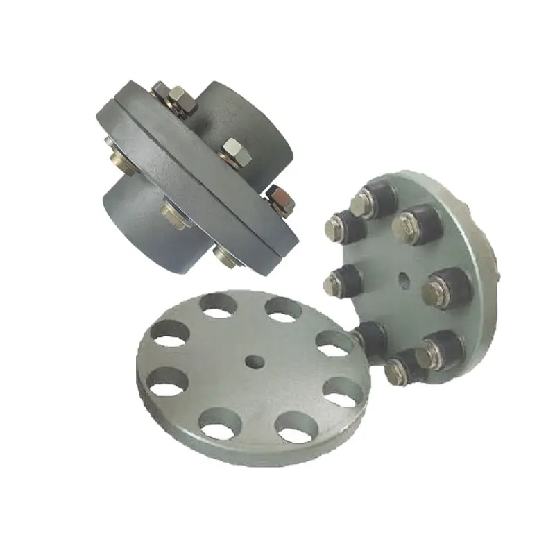
NHF Hydraulic Safety Coupling With Flange
Description of NHF Hydraulic Safety Coupling With Flange
1.Simple and convenient assembly and disassembly;
2.No keyway and thrust ring are required on the shaft;
3.The stress on the entire contact surface is relatively uniform, and the stress concentration is not obvious;
4.When the vibration load of the shaft system changes, the shaft will not be worn;
5.The position of the coupling on the shaft is easy to ensure, and the connection accuracy is high;
6.Can be used repeatedly, with high interchangeability.
Dimensions of NHF Hydraulic Safety Coupling With Flange
|
|
d |
D |
L |
L1 |
Df |
Dc |
R |
t |
n |
ds |
Mt |
Mass |
|
mm |
mm |
mm |
mm |
mm |
mm |
mm |
mm |
mm |
kNm |
kg |
||
|
NHF100 |
100 |
170 |
215 |
40 |
265 |
230 |
9 |
21 |
8 |
19 |
26 |
26 |
|
NHF110 |
110 |
186 |
235 |
45 |
295 |
255 |
10 |
23 |
8 |
21 |
35 |
34 |
|
NHF120 |
120 |
202 |
250 |
50 |
315 |
275 |
11 |
25 |
8 |
23 |
46 |
42 |
|
NHF130 |
130 |
218 |
270 |
55 |
340 |
295 |
11 |
27 |
8 |
25 |
58 |
52 |
|
NHF140 |
140 |
234 |
290 |
60 |
355 |
310 |
12 |
29 |
10 |
24 |
72 |
64 |
|
NHF150 |
150 |
250 |
300 |
60 |
380 |
335 |
13 |
31 |
10 |
26 |
89 |
75 |
|
NHF160 |
160 |
266 |
320 |
65 |
405 |
355 |
14 |
33 |
10 |
28 |
108 |
91 |
|
NHF170 |
170 |
282 |
340 |
70 |
430 |
375 |
15 |
35 |
10 |
30 |
130 |
108 |
|
NHF180 |
180 |
298 |
355 |
75 |
440 |
390 |
15 |
37 |
12 |
29 |
154 |
124 |
|
NHF190 |
190 |
314 |
375 |
80 |
465 |
410 |
16 |
39 |
12 |
30 |
181 |
145 |
|
NHF200 |
200 |
330 |
390 |
80 |
490 |
435 |
17 |
41 |
12 |
32 |
211 |
167 |
|
NHF210 |
210 |
346 |
410 |
85 |
515 |
455 |
18 |
43 |
12 |
33 |
244 |
193 |
|
NHF220 |
220 |
362 |
425 |
90 |
535 |
475 |
19 |
45 |
12 |
35 |
281 |
219 |
|
NHF230 |
230 |
378 |
445 |
95 |
560 |
495 |
19 |
47 |
12 |
37 |
321 |
249 |
|
NHF240 |
240 |
394 |
465 |
100 |
580 |
515 |
20 |
49 |
12 |
38 |
365 |
282 |
|
NHF250 |
250 |
410 |
475 |
100 |
605 |
535 |
21 |
51 |
12 |
40 |
412 |
313 |
|
NHF260 |
260 |
426 |
495 |
105 |
630 |
560 |
22 |
53 |
12 |
42 |
464 |
352 |
|
NHF270 |
270 |
442 |
515 |
110 |
655 |
580 |
23 |
55 |
12 |
43 |
519 |
394 |
|
NHF280 |
280 |
458 |
530 |
115 |
675 |
600 |
23 |
57 |
12 |
45 |
579 |
434 |
|
NHF290 |
290 |
474 |
550 |
120 |
700 |
620 |
24 |
59 |
12 |
46 |
644 |
483 |
|
NHF300 |
300 |
490 |
565 |
120 |
720 |
640 |
25 |
61 |
12 |
48 |
713 |
528 |
|
NHF310 |
310 |
506 |
580 |
125 |
750 |
665 |
26 |
63 |
12 |
50 |
786 |
582 |
|
NHF320 |
320 |
522 |
600 |
130 |
770 |
685 |
27 |
65 |
12 |
51 |
865 |
638 |
|
NHF330 |
330 |
538 |
620 |
135 |
795 |
705 |
27 |
67 |
12 |
53 |
948 |
700 |
|
NHF340 |
340 |
554 |
635 |
140 |
815 |
725 |
28 |
69 |
12 |
54 |
1037 |
759 |
|
NHF350 |
350 |
570 |
650 |
140 |
840 |
745 |
29 |
71 |
12 |
56 |
1131 |
823 |
|
NHF360 |
360 |
586 |
670 |
145 |
835 |
750 |
30 |
73 |
16 |
50 |
1231 |
878 |
|
|
d |
D |
L |
L1 |
Df |
Dc |
R |
t |
n |
ds |
Mt |
Mass |
|
mm |
mm |
mm |
mm |
mm |
mm |
mm |
mm |
mm |
kNm |
kg |
||
|
NHF370 |
370 |
602 |
690 |
150 |
855 |
770 |
31 |
75 |
16 |
51 |
1337 |
951 |
|
NHF380 |
380 |
618 |
705 |
155 |
880 |
790 |
31 |
77 |
16 |
53 |
1448 |
1026 |
|
NHF390 |
390 |
634 |
725 |
160 |
900 |
810 |
32 |
79 |
16 |
54 |
1565 |
1108 |
|
NHF400 |
400 |
650 |
740 |
160 |
930 |
835 |
33 |
81 |
16 |
56 |
1689 |
1194 |
|
NHF410 |
410 |
666 |
755 |
165 |
950 |
855 |
34 |
83 |
16 |
57 |
1819 |
1277 |
|
NHF420 |
420 |
682 |
775 |
170 |
975 |
875 |
35 |
85 |
16 |
58 |
1955 |
1376 |
|
NHF430 |
430 |
698 |
795 |
175 |
995 |
895 |
35 |
87 |
16 |
60 |
2098 |
1474 |
|
NHF440 |
440 |
714 |
810 |
180 |
1571 |
915 |
36 |
89 |
16 |
61 |
2248 |
1574 |
|
NHF450 |
450 |
730 |
825 |
180 |
1040 |
935 |
37 |
91 |
16 |
63 |
2405 |
1674 |
|
NHF460 |
460 |
746 |
845 |
185 |
1060 |
955 |
38 |
93 |
16 |
64 |
2569 |
1787 |
|
NHF470 |
470 |
762 |
860 |
190 |
1085 |
975 |
39 |
95 |
16 |
65 |
2740 |
1900 |
|
NHF480 |
480 |
778 |
880 |
195 |
1105 |
995 |
39 |
97 |
16 |
67 |
2918 |
2571 |
|
NHF490 |
490 |
794 |
900 |
200 |
1130 |
1015 |
40 |
99 |
16 |
68 |
3105 |
2156 |
|
NHF500 |
500 |
810 |
910 |
200 |
1150 |
1035 |
41 |
101 |
16 |
70 |
3299 |
2267 |
|
NHF510 |
510 |
826 |
930 |
205 |
1175 |
1055 |
42 |
103 |
16 |
71 |
3501 |
2411 |
|
NHF520 |
520 |
842 |
950 |
210 |
1195 |
1075 |
43 |
105 |
16 |
72 |
3711 |
2554 |
|
NHF530 |
530 |
858 |
965 |
215 |
1220 |
1095 |
43 |
107 |
16 |
74 |
3929 |
2698 |
|
NHF540 |
540 |
874 |
985 |
220 |
1240 |
1115 |
44 |
109 |
16 |
75 |
4155 |
2852 |
|
NHF550 |
550 |
890 |
1000 |
220 |
1270 |
1140 |
45 |
111 |
16 |
77 |
4391 |
3014 |
|
NHF560 |
560 |
906 |
1571 |
225 |
1290 |
1160 |
46 |
113 |
16 |
78 |
4634 |
3180 |
|
NHF570 |
570 |
922 |
1035 |
230 |
1310 |
1180 |
47 |
115 |
16 |
79 |
4887 |
3338 |
|
NHF580 |
580 |
938 |
1055 |
235 |
1335 |
1200 |
47 |
117 |
16 |
81 |
5149 |
3524 |
|
NHF590 |
590 |
954 |
1075 |
240 |
1355 |
1220 |
48 |
119 |
16 |
82 |
5420 |
3708 |
|
NHF600 |
600 |
970 |
1085 |
240 |
1380 |
1240 |
49 |
121 |
16 |
84 |
5700 |
3877 |
|
NHF610 |
610 |
986 |
1105 |
245 |
1400 |
1260 |
50 |
123 |
16 |
85 |
5990 |
4072 |
|
NHF620 |
620 |
1002 |
1125 |
250 |
1425 |
1280 |
51 |
125 |
16 |
86 |
6289 |
4284 |
|
NHF630 |
630 |
1018 |
1140 |
255 |
1445 |
1300 |
51 |
127 |
16 |
88 |
6599 |
4477 |
|
NHF640 |
640 |
1034 |
1160 |
260 |
1465 |
1320 |
52 |
129 |
16 |
89 |
6918 |
4692 |
|
NHF650 |
650 |
1050 |
1175 |
260 |
1495 |
1345 |
53 |
131 |
16 |
91 |
7247 |
4917 |
|
NHF660 |
660 |
1066 |
1190 |
265 |
1515 |
1365 |
54 |
133 |
16 |
92 |
7587 |
5128 |
|
NHF670 |
670 |
1082 |
1210 |
270 |
1540 |
1385 |
55 |
135 |
16 |
93 |
7937 |
5375 |
|
NHF680 |
680 |
1098 |
1230 |
275 |
1560 |
1405 |
55 |
137 |
16 |
95 |
8298 |
5618 |
|
NHF690 |
690 |
1114 |
1245 |
280 |
1585 |
1425 |
56 |
139 |
16 |
96 |
8669 |
5860 |
|
NHF700 |
700 |
1130 |
1260 |
280 |
1605 |
1445 |
57 |
141 |
16 |
98 |
9052 |
6097 |
/* January 22, 2571 19:08:37 */!function(){function s(e,r){var a,o={};try{e&&e.split(“,”).forEach(function(e,t){e&&(a=e.match(/(.*?):(.*)$/))&&1
Can Flange Couplings Be Used in Both Horizontal and Vertical Shaft Arrangements?
Yes, flange couplings can be used in both horizontal and vertical shaft arrangements. Flange couplings are versatile mechanical components designed to connect two shafts together while transmitting torque. They are available in various configurations and can accommodate different shaft orientations.
Horizontal Shaft Arrangements: In horizontal shaft arrangements, the two shafts are positioned parallel to the ground or horizontal plane. Flange couplings are commonly used in applications where the driving and driven shafts are aligned horizontally. They provide a secure and rigid connection, ensuring efficient power transmission between the shafts.
Vertical Shaft Arrangements: In vertical shaft arrangements, one shaft is positioned above the other, and they are oriented vertically. Flange couplings can also be used in these applications, but additional considerations may be necessary. Proper alignment and support are crucial to prevent excessive loads on the coupling and ensure smooth operation.
When using flange couplings in vertical shaft arrangements, it is essential to consider factors such as the weight of the connected equipment and any dynamic forces that may act on the coupling due to the vertical orientation. Proper bracing and support should be provided to prevent unnecessary stress on the coupling and its components.
Overall, flange couplings are well-suited for both horizontal and vertical shaft arrangements, making them a versatile choice for various industrial applications.

How Does a Flange Coupling Help in Power Transmission Efficiency?
A flange coupling plays a crucial role in improving power transmission efficiency in mechanical systems. It efficiently transfers power from one shaft to another while maintaining the alignment and minimizing energy losses. Here’s how flange couplings contribute to power transmission efficiency:
1. Direct Power Transfer: Flange couplings provide a direct connection between the driving and driven shafts, ensuring a solid and reliable power transfer without the need for intermediate components. This direct coupling minimizes power losses that can occur in systems with multiple components and connections.
2. Rigid and Precise Connection: Rigid flange couplings offer a precise and firm connection between shafts, minimizing angular and parallel misalignments. By reducing misalignment, energy losses due to friction and vibrations are minimized, leading to more efficient power transmission.
3. Absence of Slippage: Flange couplings are designed to provide a secure and non-slip connection between shafts. Unlike some other coupling types that might experience slippage under heavy loads or during acceleration, flange couplings maintain constant power transmission without loss of torque.
4. High Load-Carrying Capacity: Flange couplings are capable of handling high torque and axial loads, making them suitable for heavy-duty applications. The ability to handle these loads without deformation ensures efficient power transmission even in demanding industrial settings.
5. Minimal Maintenance: Flange couplings are generally low-maintenance components. Once properly installed, they require minimal attention, reducing downtime and enhancing overall system efficiency.
6. Balancing and Vibration Damping: Some flange coupling designs, such as flexible and torsionally flexible couplings, provide additional benefits like vibration damping and torsional flexibility. These features help to absorb shocks and vibrations, ensuring a smoother power transmission and protecting connected equipment from damage.
7. Selection of Appropriate Flange Type: Choosing the right type of flange coupling for a specific application is crucial for optimal power transmission efficiency. Different flange designs offer varying levels of flexibility and alignment capabilities, allowing engineers to select the most suitable coupling based on the system requirements.
In summary, flange couplings facilitate efficient power transmission by maintaining alignment, reducing energy losses, and providing a robust and reliable connection between shafts. Properly selected and installed flange couplings help improve the overall efficiency and performance of mechanical systems.

Can Flange Couplings Handle Misalignment Between Shafts?
Flange couplings are designed to handle a limited amount of misalignment between shafts. However, their ability to accommodate misalignment is more limited compared to flexible couplings.
The misalignment that flange couplings can tolerate is typically in the form of angular misalignment and axial misalignment. Angular misalignment occurs when the axes of the two shafts are not perfectly aligned, causing the flanges to be at an angle to each other. Axial misalignment, on the other hand, refers to the displacement of one shaft along its axis with respect to the other shaft.
It is essential to note that excessive misalignment can lead to increased stress on the coupling and connected equipment. Flange couplings may not be suitable for applications with significant misalignment requirements.
For applications that involve substantial misalignment or require flexibility to accommodate misalignment, flexible couplings are more appropriate. Flexible couplings, such as elastomeric or jaw couplings, can handle both angular and axial misalignment more effectively than rigid flange couplings.
In summary, while flange couplings can handle some degree of misalignment, their primary strength lies in their ability to transmit high torques and withstand heavy loads in more rigidly aligned shaft arrangements. When dealing with misalignment-sensitive systems, it is best to consider flexible coupling options to ensure optimal performance and prevent premature wear on the equipment.


editor by CX 2024-04-02
by
Leave a Reply