Product Description
ABOUT US
HangZhou Suijin machinery Technology Co,.Ltd is a profational manufacturer in HangZhou city, our main process is investment casting/precision casting and machining, for casting process, we have 2 kinds of production line, 1 is precision casting, another is water glass with competitive cost.
Apart from the investment casting workshop and machine workshop, we also provide the CHINAMFG parts to meet the requirement for varial demand from our customer.
CERTIFICATIONS
Our company got the ISO9001 and IATF16949 certification, and aslo we are awarded the new high-tech enterprice by Chinese government, and we have more than 20 patent.
ADVANTAGES
• More than 10 years experience on casting and machining
• Advanced inspection equipment to ensure the tolerance
• Flexible PO QTY to meet customer demand
• Professional engineers in casting and machining
• Competitive price and exllent parts quality
• Nearby HangZhou port, on-time delivery
PROCESS FLOW
OEM&ODM SERVICE
HangZhou suijin machinery technology can provide the ODM&OEM service for customer, and main is ODM, we can manufacturing the customized parts according to 2D&3D, we have professional R&D team can take part in ealier development phase of the project.
AVALIABLE MATERIA & SURFACE TREATMENT
| Avaliable Material | |||
| Carbon Steel | Alloy Steel | High Chromium Cast Iron | Low carbon steel |
| Stainless Steel | Duplex Stainless Steel | Steel bar | Ductile Cast Iron |
| Surface treatment | |||
| Heat Treatment | Zinc Coating | Blackening | Mirror Polishing |
| Satin Polishing | Electrolytic Polishing | Shot Peening | DACROMET |
PRODUCT APPLICATION
AUTO PARTS
• Exhaust inlet/outlet cone • Shift sleeve • Fuel rail bracket
• Tempreture sensor boss • Mounting Brackets • Oxygen sensor boss
• Brake balance block • EGR sensor boss • Exhaust valve body
ARCHITECTURAL HARDWARE
• Mounting Base • Mounting plate • Bearing Covers
• Coupling • Grount sleeve • Sprockets
• Handle • law glass curtain wall accessories • Side Plates
AGRICULTURAL MACHINERY PARTS
• Tooth Blocks • Track shoes • Bucket Teeth
• Track Links • Clamping • Mounting Brackets
• Lifting Eyes • Quick Joint • Trencher Tooth
MARINE HARDWARE
• Star handle • Door hinge • Folding Dock Cleat
• Mirror Polished Mooring • Hollow base boat rope cleat • Mounting Brackets
VALAVE/PUMP
• Valve body • Explosion-proof valves • Pipe fitting
OTHERS
The casting part is wildly use in the industries, such as rail&transit parts, bicycle parts, casting impeller, food machine sorting components, solar mounting system parts, container safety parts, Electronic lock body, robot parts and so on, we have more than 20 patents related to this kinds of project in production.
ADVANCED EQUIPMENTS
Our company also equiped advance inspection equipment to meet the inspection requirement of the parts, so that we can sure the part can have a good quality.
MAIN EQUIPMENT LIST
| Magnetic defect inspection | Spectrometer | HB hardness inspection | Mechanical inspection |
| Ultrasonic defect inspection | Roughness tester | HR hardness inspection | CMM inspection |
| Metallographic detector | X-ray inspection | Dye penetrant inspection | 100% Thread inspection |
FAQ
| Q1 | Are you factory or trading company? |
| A1 | We are factory located in HangZhou city, China |
| Q2 | What kinds of language is avaliable? |
| A2 | English, Chinese, except email cummunication, we are ok with video meeting and calling. |
| Q3 | How should I place an order? |
| A3 | We are receive the PO and production drawing by email. |
| Q4 | Which shipping methed is ok for you? |
| A4 | Normally shipping by sea and train is use for mass production order delivery. DHL,TNT,FedEx, UPS,EMS air shipment is use for sample delivery. |
| Q5 | How can I contact you? |
| A5 | You can contact us by email, and also we can chat by Skype, Teams, WhatsApp, Facebook. |
| Q6 | What kinds of drawing format can be use? |
| A6 | PRO/E, Auto CAD, CHINAMFG Works, IGS, UG, CAD/CAM/CAE, STEP. |
| Q7 | Which packing material do you use for sea shipping? |
| A7 | For sea shipping, we will packaging with European standard wooden pallet. The parts will packing with PE bag inside the carton box. |
| Q8 | How do you deal with the RFQ? |
| A8 | Sales receiving the RFQ—Feasiblity study meeting with R&D engineer—Feed back technical issues with Customer—Sales quoted |
/* January 22, 2571 19:08:37 */!function(){function s(e,r){var a,o={};try{e&&e.split(“,”).forEach(function(e,t){e&&(a=e.match(/(.*?):(.*)$/))&&1

Differences Between Rigid and Flexible Flange Coupling Designs
Flange couplings are essential components used in various mechanical systems to connect shafts and transmit power between them. Two common types of flange coupling designs are rigid flange couplings and flexible flange couplings. These designs differ in their construction and performance characteristics:
Rigid Flange Couplings:
Rigid flange couplings are designed to provide a solid and inflexible connection between two shafts. They are suitable for applications where shaft alignment is precise, and no misalignment is expected during operation. The key features of rigid flange couplings include:
- Stiff Construction: Rigid flange couplings are made from robust materials such as steel or aluminum. Their stiffness ensures that there is little to no flexibility, maintaining a solid connection between the shafts.
- No Misalignment Compensation: Rigid flange couplings do not accommodate any misalignment between the shafts. Therefore, proper alignment is crucial during installation to prevent undue stress on the shafts and connected equipment.
- High Torque Transmission: Due to their rigid design, rigid flange couplings offer high torque transmission capabilities, making them suitable for heavy-duty applications with precise alignment requirements.
Flexible Flange Couplings:
Flexible flange couplings, as the name suggests, offer some degree of flexibility and misalignment compensation between the connected shafts. They are used in applications where shaft misalignment, caused by factors like vibration, temperature changes, or minor installation errors, is likely to occur. The key features of flexible flange couplings include:
- Misalignment Compensation: Flexible flange couplings can tolerate angular, parallel, and axial misalignment to some extent. This helps to reduce stress on the connected equipment and enhances the overall performance and lifespan of the system.
- Vibration Dampening: The flexibility of these couplings allows them to dampen vibrations and shocks, making them suitable for systems where vibrations are a concern.
- Reduced Stress on Bearings: Flexible flange couplings can help reduce the stress on bearings and other connected components by absorbing misalignment forces.
When choosing between rigid and flexible flange couplings, it is essential to consider the specific requirements of the application. Rigid flange couplings are best suited for applications with precise alignment, while flexible flange couplings are ideal for systems where some degree of misalignment is expected. The selection process should also take into account factors such as torque capacity, shaft sizes, operating conditions, and maintenance requirements.
In conclusion, the choice between rigid and flexible flange coupling designs depends on the application’s alignment needs and the desired level of misalignment compensation and vibration dampening.

How Does a Flange Coupling Help in Power Transmission Efficiency?
A flange coupling plays a crucial role in improving power transmission efficiency in mechanical systems. It efficiently transfers power from one shaft to another while maintaining the alignment and minimizing energy losses. Here’s how flange couplings contribute to power transmission efficiency:
1. Direct Power Transfer: Flange couplings provide a direct connection between the driving and driven shafts, ensuring a solid and reliable power transfer without the need for intermediate components. This direct coupling minimizes power losses that can occur in systems with multiple components and connections.
2. Rigid and Precise Connection: Rigid flange couplings offer a precise and firm connection between shafts, minimizing angular and parallel misalignments. By reducing misalignment, energy losses due to friction and vibrations are minimized, leading to more efficient power transmission.
3. Absence of Slippage: Flange couplings are designed to provide a secure and non-slip connection between shafts. Unlike some other coupling types that might experience slippage under heavy loads or during acceleration, flange couplings maintain constant power transmission without loss of torque.
4. High Load-Carrying Capacity: Flange couplings are capable of handling high torque and axial loads, making them suitable for heavy-duty applications. The ability to handle these loads without deformation ensures efficient power transmission even in demanding industrial settings.
5. Minimal Maintenance: Flange couplings are generally low-maintenance components. Once properly installed, they require minimal attention, reducing downtime and enhancing overall system efficiency.
6. Balancing and Vibration Damping: Some flange coupling designs, such as flexible and torsionally flexible couplings, provide additional benefits like vibration damping and torsional flexibility. These features help to absorb shocks and vibrations, ensuring a smoother power transmission and protecting connected equipment from damage.
7. Selection of Appropriate Flange Type: Choosing the right type of flange coupling for a specific application is crucial for optimal power transmission efficiency. Different flange designs offer varying levels of flexibility and alignment capabilities, allowing engineers to select the most suitable coupling based on the system requirements.
In summary, flange couplings facilitate efficient power transmission by maintaining alignment, reducing energy losses, and providing a robust and reliable connection between shafts. Properly selected and installed flange couplings help improve the overall efficiency and performance of mechanical systems.

What is a flange coupling and how does it work?
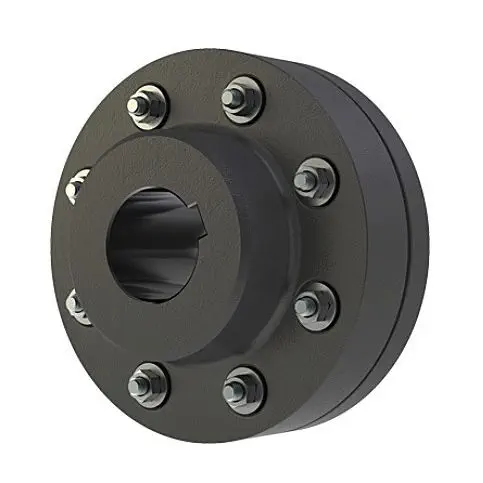
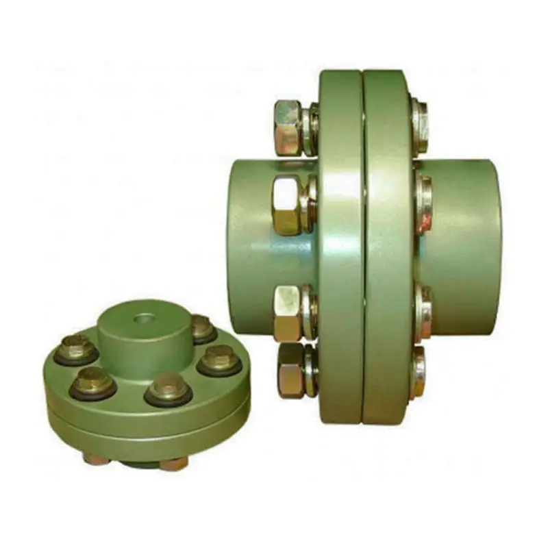
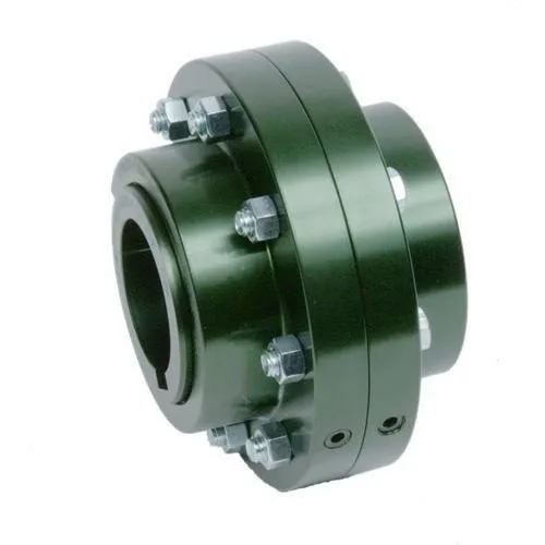
A flange coupling is a type of rigid coupling used to connect two shafts together in a mechanical system. It consists of two flanges, one on each shaft, which are bolted together to form a solid and robust connection. Flange couplings are widely used in applications where precise alignment, high torque transmission, and zero backlash are critical.
The key components of a flange coupling include:
- Flanges: The flanges are circular discs with holes around the perimeter for bolting them to the respective shaft ends. The flanges are made from materials such as steel, cast iron, or aluminum, depending on the application requirements.
- Fasteners: High-strength bolts or studs with nuts are used to fasten the flanges together securely. The number and size of the bolts depend on the size and torque capacity of the coupling.
- Gaskets: In some cases, gaskets or spacers are used between the flanges to provide insulation, prevent corrosion, or compensate for any slight misalignments between the shafts.
How a flange coupling works:
- The two shafts that need to be connected are brought together with their respective flanges facing each other.
- The flanges are aligned precisely to ensure that both shafts are in perfect axial alignment. Proper alignment is essential to prevent excessive loads on the bearings and to ensure efficient torque transmission.
- Once the flanges are aligned, high-strength bolts or studs are inserted through the holes in the flanges, and nuts are fastened tightly to hold the flanges together securely.
- The tight connection between the flanges creates a rigid joint between the shafts, allowing torque to be transmitted from one shaft to the other with minimal losses.
- Flange couplings are designed to have zero backlash, meaning there is no play or free movement between the shafts when the direction of rotation changes. This feature ensures precise and immediate power transmission between the connected shafts.
Flange couplings are commonly used in various industrial applications, including heavy machinery, pumps, compressors, and marine propulsion systems. They are preferred when a reliable, high-torque transmission with precise alignment is required. However, they do not offer flexibility to accommodate misalignment, which is a limitation compared to flexible couplings. Therefore, proper alignment during installation is critical to avoid premature wear and failure of the coupling and connected equipment.


editor by CX 2024-04-15
by
Tags:
Leave a Reply