Product Description
Product Description
FM/UL Rigid or Flexible Couplings/Reducing Tee/Mechanical Tee/Elbow/Cross/Flange/Reducer/Cap/Grooved Pipe Fittings Grooved Couplings
FM/UL Rigid or Flexible Couplings/Reducing Tee/Mechanical Tee/Elbow/Cross/Flange/Reducer/Cap/Grooved Pipe Fittings Grooved Couplings
Ductile iron grooved pipe fittings and couplings (FM and UL approved) mainly including 2 kinds of grooved products:
(1) the pipe fittings function on connecting and sealing such as rigid coupling, flexible coupling, mechanical tee and grooved flange,
(2) the pipe fittings function on connecting and transition such as bend, tee, cross, reducer.
Specification
| Name | Rigid coupling, Flexible coupling, 90° Elbow, 45° Elbow, 22.5° Elbow, 11.25° Elbow, Split Flange, Adaptor Flange, Cap | |
| Tee, Reducing Tee(Grooved/Threaded), Mechnical Tee(Grooved/Threaded), U-bolted Mechnical Tee | ||
| Cross, Reducing Cross(Grooved/Threaded), Mechnical Cross(Grooved/Threaded) | ||
| Reducer(Grooved/Threaded), Grooved Eccentric Reducer | ||
| H.S. CODE | 735710000 | |
| Technology | Casting | |
| Connections | Grooved-Thread End, Grooved End | |
| Pressure Rate | 300PSI / 2.07MPa | |
| Size | 1” – 12” | |
| Pipe O.D. | 33.7MM – 323.9MM | |
| Surface Finish | Epoxy Powder,Painting,Galvanization,Dacromet (in Red/Orange/Blue/White Color) | |
| Design Standard | American Standard | ANSI/ASTM |
| European Standard | EN | |
| British Standard | BS | |
| Germany Standard | DIN | |
| Japanese Standard | JIS | |
| ISO Standard | ISO | |
| Thread Standard | ASME B.1.20.1 / EN15716 / DIN2999 / ISO7-1 / ISO228 / IS554 / BS EN15716 / BS 21.173 | |
| Material Standard | Ductile Iron confirms to ASTM A-536 Gr65-45-12,EN1563,JIS G5502,QT450-12 | |
| Gasket Material | EPDM,NBR or Silicon Rubber | |
| Bolts & Nuts | ISO 898-1class 8.8 | |
| Flanges Standard | PN series or Class series | |
| Packages | Plywood Cases or Plywood Pallets or Boxes | |
| Application | Fire Fighting System,Petrochemical & Gas Industry,Chemical,Machinery,Electric Power,Construction Water Works,Valve Industry,etc. | |
| Advantages | High Quality + Ready Stock + Faster Delivery + Customized | |
| Brand | LMP | |
| Certificate | ISO9001,API,CE,UL/FM | |
Company Profile
We are a leading manufacturer of pipe fittings and valves establised in 1996
1. We have over 20 years experience in exporting pipeline products.
2. 5 factories,complete 100+ projects every year.
3. Your 1 more good choice for better customer service.
Certifications
FAQ
/* January 22, 2571 19:08:37 */!function(){function s(e,r){var a,o={};try{e&&e.split(“,”).forEach(function(e,t){e&&(a=e.match(/(.*?):(.*)$/))&&1

Proper Installation and Alignment of Flange Couplings
Installing and aligning a flange coupling properly is crucial to ensure its optimal performance and to prevent premature wear or failure. Here are the steps to follow for a successful installation:
- Prepare the Components: Before starting the installation, ensure that all the components, including the flange coupling, shafts, and fasteners, are clean and free from dirt or debris. Inspect the coupling for any visible damage or defects.
- Check Shaft Alignment: Verify the alignment of the shafts before installing the flange coupling. Misalignment can lead to increased stresses on the coupling and other connected equipment.
- Use Proper Lubrication: Apply the recommended lubricant to the contact surfaces of the flange coupling. Proper lubrication reduces friction and wear, enhancing the coupling’s lifespan.
- Align the Flange Coupling: Position the flange coupling between the shafts and ensure that the bolt holes are aligned with the corresponding holes in the shafts.
- Insert Fasteners: Insert the bolts or screws through the bolt holes and hand-tighten them. Avoid fully tightening any fasteners at this stage.
- Check Runout: Measure the runout of the coupling during rotation to verify that it is within acceptable limits. Excessive runout indicates a misaligned coupling.
- Properly Torque Fasteners: Using a torque wrench, tighten the fasteners in a cross-pattern to the manufacturer’s recommended torque values. This ensures even distribution of the load and prevents distortion of the flange coupling.
- Recheck Alignment: After torquing the fasteners, recheck the shaft alignment to ensure it has not shifted during the tightening process.
- Inspect the Assembly: Conduct a final visual inspection of the installed flange coupling and surrounding components to verify that everything is properly aligned and secured.
- Perform Test Run: Run the equipment with the newly installed flange coupling under no-load conditions initially to check for any unusual vibrations or noises.
- Monitor Performance: During the initial operation and throughout regular use, monitor the flange coupling’s performance and check for signs of wear, misalignment, or other issues.
Professional Installation: If you are unsure about the installation process or need to install a flange coupling in a complex system, consider seeking assistance from a qualified professional or coupling manufacturer’s technical support team. Proper installation is essential for ensuring the long-term reliability and performance of the flange coupling and the connected equipment.

What Role Does a Flange Coupling Play in Minimizing Wear and Tear on Connected Components?
A flange coupling plays a critical role in minimizing wear and tear on connected components in rotating machinery. It accomplishes this by effectively transmitting torque between two shafts while accommodating misalignment and reducing the transmission of shock and vibration. Here’s how a flange coupling achieves these benefits:
- Misalignment Compensation: Flange couplings are designed to accommodate both angular and parallel misalignment between the shafts they connect. As machinery operates, shafts may experience slight misalignment due to thermal expansion, manufacturing tolerances, or other factors. The flexible nature of certain flange coupling designs allows them to compensate for these misalignments, preventing excessive stress on connected components that could lead to wear.
- Shock and Vibration Damping: Flange couplings help dampen shock and vibration during machinery operation. When a machine experiences sudden impacts or vibrations, the flexibility of some flange coupling types absorbs and disperses these forces. By reducing the transfer of shocks and vibrations to the connected components, flange couplings protect the machinery from excessive stress and premature wear.
- Smooth Torque Transmission: Flange couplings provide a smooth and reliable means of transmitting torque from one shaft to another. The secure connection between the two shafts ensures that torque is efficiently transmitted without slippage or sudden jolts. This smooth torque transmission helps prevent unnecessary wear on the shafts and other connected components.
- Reduced Maintenance: By minimizing wear and tear on connected components, flange couplings contribute to reduced maintenance requirements. When components experience less stress and wear, their lifespan is extended, resulting in fewer maintenance interventions and decreased downtime for repairs or replacements.
- Protection Against Overloads: In cases of sudden overloads or torque spikes, flange couplings can act as a safety feature by allowing some degree of slippage or disengagement. This protects the connected machinery from potential damage caused by excessive loads.
In summary, a flange coupling’s ability to compensate for misalignment, dampen shocks and vibrations, provide smooth torque transmission, and protect against overloads makes it a crucial component in minimizing wear and tear on connected machinery. By choosing the appropriate flange coupling design for a specific application, engineers can enhance the reliability and longevity of the entire system while reducing maintenance and downtime costs.

What is a flange coupling and how does it work?
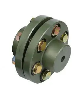
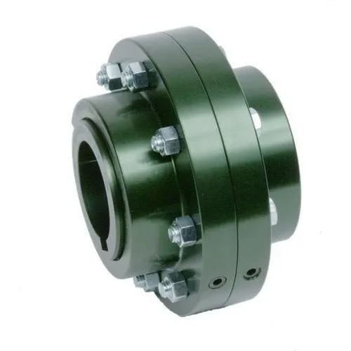
A flange coupling is a type of rigid coupling used to connect two shafts together in a mechanical system. It consists of two flanges, one on each shaft, which are bolted together to form a solid and robust connection. Flange couplings are widely used in applications where precise alignment, high torque transmission, and zero backlash are critical.
The key components of a flange coupling include:
- Flanges: The flanges are circular discs with holes around the perimeter for bolting them to the respective shaft ends. The flanges are made from materials such as steel, cast iron, or aluminum, depending on the application requirements.
- Fasteners: High-strength bolts or studs with nuts are used to fasten the flanges together securely. The number and size of the bolts depend on the size and torque capacity of the coupling.
- Gaskets: In some cases, gaskets or spacers are used between the flanges to provide insulation, prevent corrosion, or compensate for any slight misalignments between the shafts.
How a flange coupling works:
- The two shafts that need to be connected are brought together with their respective flanges facing each other.
- The flanges are aligned precisely to ensure that both shafts are in perfect axial alignment. Proper alignment is essential to prevent excessive loads on the bearings and to ensure efficient torque transmission.
- Once the flanges are aligned, high-strength bolts or studs are inserted through the holes in the flanges, and nuts are fastened tightly to hold the flanges together securely.
- The tight connection between the flanges creates a rigid joint between the shafts, allowing torque to be transmitted from one shaft to the other with minimal losses.
- Flange couplings are designed to have zero backlash, meaning there is no play or free movement between the shafts when the direction of rotation changes. This feature ensures precise and immediate power transmission between the connected shafts.
Flange couplings are commonly used in various industrial applications, including heavy machinery, pumps, compressors, and marine propulsion systems. They are preferred when a reliable, high-torque transmission with precise alignment is required. However, they do not offer flexibility to accommodate misalignment, which is a limitation compared to flexible couplings. Therefore, proper alignment during installation is critical to avoid premature wear and failure of the coupling and connected equipment.


editor by CX 2024-04-15
Leave a Reply